DIY FPV Diversity Controller – Development step 4
This is part of a series of blog posts in which I show you how I develop a DIY FPV diversity controller. In this step I have build up the finished circuit on a breadboard. It already uses the ATtiny85 micro controller and is therefore fully self contained. Read more below…
In the previous steps I was using my Arduino UNO to develop the software and circuit. Now I have successfully uploaded my diversity software to an Atmel ATtiny85 micro controller, which makes the circuit on the breadboard fully self contained.

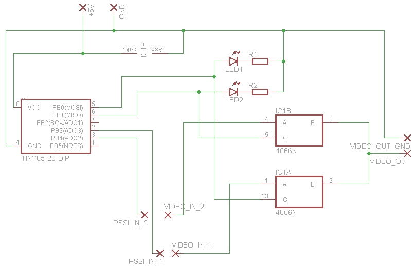
As you can see from the schematics above everything is now neatly connected together. Only the power and of course the video and RSSI input is supplies externally. An ATtiny85 now takes over the tasks of the Arduino.
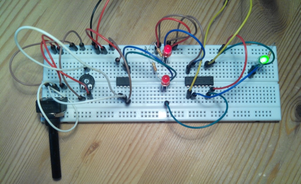
Let’s see how this looks on the breadboard:

I had to re-arrange a few thing from the previous parts to fit the ATtiny in there. But not much has changed:
- On the left there are still the two potentiometers that server as RSSI inputs during testing.
- The RSSI inputs are fed via the two white cables to the analog input pins of the ATtiny.
- A green and a blue cable is connected to the digital output pins of the ATtiny on the top. My software which runs on the ATtiny switches either of the to ON, depending on which of the to RSSI inputs is higher.
From here on the circuit is the same as in the previous steps: The green and a blue cable leaving the ATtiny are connected to LEDs which indicate which of the two is active. At the same time these two signals are forwarded to the 4066 electronic switch which is fed with the two video input signals (the yellow wires coming from the top). Depending on which of the two signals is HIGH the switch will pass one of the two input signals to the common output. At the output side there is currently a green LED connected.
Visit http://bitbucket.org/rgruber/fpv-diversity for all resources of this project.
You can find the source code, diagrams and photos there.
You might also want to take a look at this page were I have an overview of this project.
Hi,, where is the rssi located on the walkera rx702. Please send me what you can. I need the rssi from the rx702 to the osd system I’m using. Thanx Kevin
The RX702 is a rc control receiver. RSSI is (as far as I know) only available on video receivers.