DIY FPV Diversity Controller – Development step 2
This is part of a series of blog posts in which I show you how I develop a DIY FPV diversity controller. In the first step the main circuit was set up. In this step I will now introduce a new component: a 4066 electronic switch. The switch will be controlled by the Arduino and it will switch between two input sources (the video inputs from the receivers) to a common output. Read more below…
If you haven’t yet read the post about step 1 I strongly encourage you to do so, because this is all building on top of step 1.
So as we set up the main circuit with the Arduino in the last step we are now capable of reading the RSSI input values and decide which of the two is higher. Also two LEDs are already in place to signal which of the two was chosen by the Arduino.
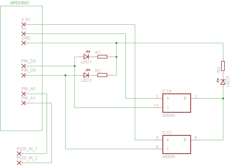
In this step we’ll add a switch. As it’s name already tells this component will do the switching between the video inputs. In order to do so the Arduino will tell the switch which of the two input source should be patched through to the output of the circuit. Let’s take a look at the schematics:

As you can see the left part did not change at all since step 1. There is still the Arduino which gets the RSSI input from below and output on either D8 or D9 pin to the LEDs. What’s new is that we grab both output lines before the LEDs and feed them to the 4066 switches on the bottom right. Don’t let the schematics fool you, while there are two components on the drawing it will actually only be a single IC component in the circuit. The 4066 switch contains four independent switches, and two of them are shown here in the schematics. You can also tell by the small numbers on the connections of the two switchs. Those are the actual pin numbers of the 4066 component. So switch IC1A will connect pin 1 and pin 2 if the control input on pin 13 is HIGH. The second switch IC1C will connect pin 8 and pin 9 if the control pin 6 is HIGH.
The output of both switches (ping 2 and pin 9) is hooked up to a LED (LED3). Again this is for testing and development. In the finished product there will be a connector for a screen or goggles. And the input for the switches is either 5V for pin 1 or 3.3V for pin 8, in the finished product that will be the video input of the two receivers. The software in the Arduino will ensure that always only one switch will be closed at any time. So in this testing setup the LED3 will be feed by either 5V from switch IC1A or it will be fed by 3.3V from switch IC1C.
So how is the Arduino controlling the two switches? From step 1 we already have two dedicated outputs (D8 and D9 on the Arduino). So all we need to do is grab those an use them to control the switches. So if the Arduino will set D8 to HIGH, the switch IC1A will connect its pin 1 and pin 2. If the Arduino sets D9 to HIGH, the switch IC1C will connect its pin 8 and pin 9.
In this testing setup the LED3 will light brighter (due to the 5V) if RSSI_IN_1 is the higher value, because then switch IC1A will be closed by the Arduino. And vice versa, it will light a bit dimmer (due to the 3.3V) if RSSI_IN_2 is the higher value, because then switch IC1C will be closed.
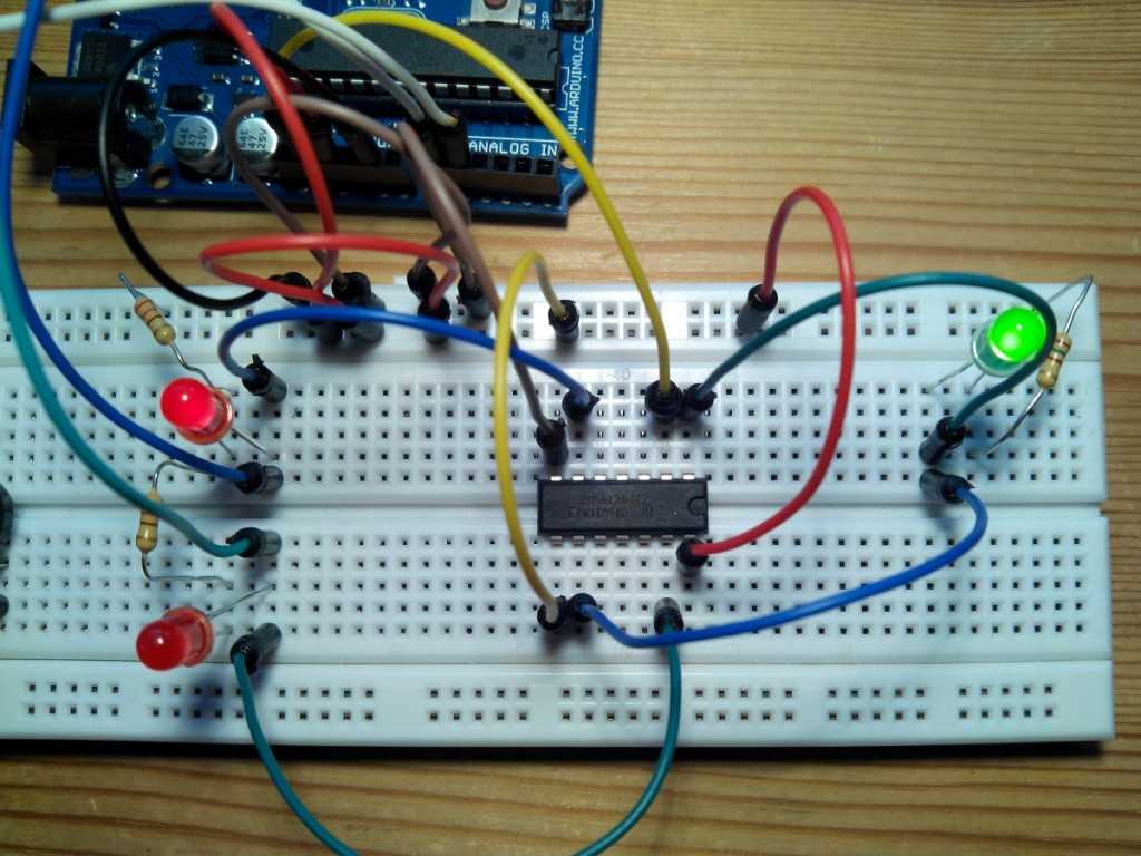
Let’s see how this looks on the bread board:

Also on the breadboard not much has changes. There are still the two white wires that feed the RSSI values into the Arduino (on the top left of the image). And the green and blue wires are the output pins of the Arduino (on the left of the image next to the LEDs). What’s new is the 4066 switch in the center and the green LED (representing the output of the diversity controller) on the right.
So let’s take a look at the 4066 switch a bit closer. Of course it needs power, so it’s connected to the 5V and GND rail of the breadboard. Those are the red wire at pin 14 and the brown wire at pin 7. The two control pins (pin 6 and pin 13) are hooked up to the output of the Arduino. On the left of the image you see the blue and green wires come in from the Arduino, those are then connected with matching color wires to the control pins of the 4066. The two yellow wires represent the video input from the two receivers. For this testing setup they are hooked up to 5V and the other to 3.3V. They are connected to the input pins of the switch (pin 1 and pin 8). On the output side of the switch (pin 2 and pin 9) a green LED was connected.
At the image above you see the upper red LED is light up. That means that the Arduino chose the second RSSI input as highest value. That also means that the control pin 6 of the switch will be feed with the HIGH from the Arduino. This results in the switch connecting the pins 8 and 9. While at the same time the lower LED is dark because it’s RSSI input is not the highest value. Therefore the switch control pin 13 is LOW, resulting in the pins 1 and 2 being disconnected. So in the picture current is running from the 5V rail on the top of the breadboard, through the yellow wire to pin 8 of the switch. Because pin 8 is internally connect to pin 9 and the switch is closed, the current can pass and will run though the green LED.
Visit http://bitbucket.org/rgruber/fpv-diversity for all resources of this project.
You can find the source code, diagrams and photos there.
You might also want to take a look at this page were I have an overview of this project.
Very nice article. I definitely love this site. Keep writing!