DIY FPV Diversity Controller – Development step 3
This is part of a series of blog posts in which I show you how I develop a DIY FPV diversity controller. But this post can also stand on it’s own. This time I show you how to program an Atmel ATtiny microchip using an Arduino UNO. Read more below…
An Atmel ATtiny chip will be the brain of my DIY FPV Diversity Controller. In this step of the development I will use my Arduino UNO to program the ATtiny chip. As you know I developed the diversity software on a breadboard using the Arduino UNO. The nice thing is that I can directly upload the same software (maybe with a few changes, like e.g. pin numbers) to an ATtiny chip that will than work standalone in my diversity controller.
Let’s start with the needed software and parts:
- Well obviously you’ll need an Arduino UNO as well as the Arduino IDE. I’m using IDE version 1.0.5 at the time I write this post.
- Next to that you need a small zip file containing some configuration stuff to tell the Arduino IDE how to work with the ATtiny chip.This can be downloaded from here: http://github.com/damellis/attiny/archive/master.zip
- You need a supported ATtiny chip. I’m using the ATtiny85. Supported are: ATtiny45, ATtiny85, ATtiny44 or ATtiny84
- A 10uF capacitor
I’ll give you a brief summary in form of a step by step guide. A very detailed description can be found at the website of the MIT High-Low Tech group. Those are the guys that created the zip file you downloaded above.
Let’s start with some preparations that you only need to do once:
- Extract the zip file you downloaded above. It should contain a folder called “attiny-master” which contains a “attiny” folder.
- Go to the place where your Arduino IDE stores the sketches.
Something like C:\Users\<USERNAME>\Documents\Arduino - Create a folder called “hardware” there. Maybe it already exists, then you can just move on.
- Copy the “attiny” (not the “attiny-master”) folder into the “hardware” folder
- It should now look like this C:\Users\<USERNAME>\Documents\Arduino\hardware\attiny
- Start your Arduino IDE. In case you already had it running please restart it for the changes to take effect.
- The Tools -> Board menu should now list the possible ATtiny chips. But do not(!) change anything yet.
Now how to upload a program to the ATtiny85? You need to connect your Arduino UNO to the ATtiny like this. But do not(!) attach the capacitor yet:
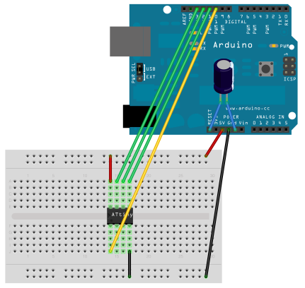
- Upload the ArduinoISP sketch to your Arduino. You can find the sketch in the File -> Examples menu. Leave your Arduino connected to the PC.
- Most Arduino UNO need a 10uF capacitor connected between RESET and GND (see image above) to be able to use them as programmer. Note: You only need to attach this capacitor when you want to upload a sketch to the ATtiny. Remove it when you want to upload a sketch to your Arduino Board.
- Now open your sketch in the Arduino IDE that should be uploaded to the ATtiny. For testing you can open the “Blink” sketch from the examples menu and change the led pin from 13 to 0(zero).
- Choose the appropriate entry from the Tools -> Board menu. In my case it’s “ATtiny85 (internal 1MHz clock)”
- Choose “Arduino as ISP” from the Tools -> Programmer menu.
- Upload the sketch as you normally do.
But because you choose a different board and your Arduino as ISP what will happen now is the following: The IDE sends the program to the Arduino which will kind of “forward” it to the connected ATtiny chip where it will be stored. - You can not disconnect all wires from your ATtiny and the Arduino UNO. Just leave the power and GND connected, or power your ATtiny from a different 5V power source.
- Connect a LED from the ATtiny’s pin zero to GND. The LED should blink every second.
When you look down on the chip, Pin zero is the ATtiny85’s lowest right leg. That’s the one that you connected to Arduino Pin 11 during the programming (see image above).
Visit the website of the MIT High-Low Tech group you can find more details including a drawing with all the pin numbers of the ATtiny45, ATtiny85, ATtiny44 and ATtiny84 there.
Leave a Reply