DIY FPV Diversity Controller – Development step 5
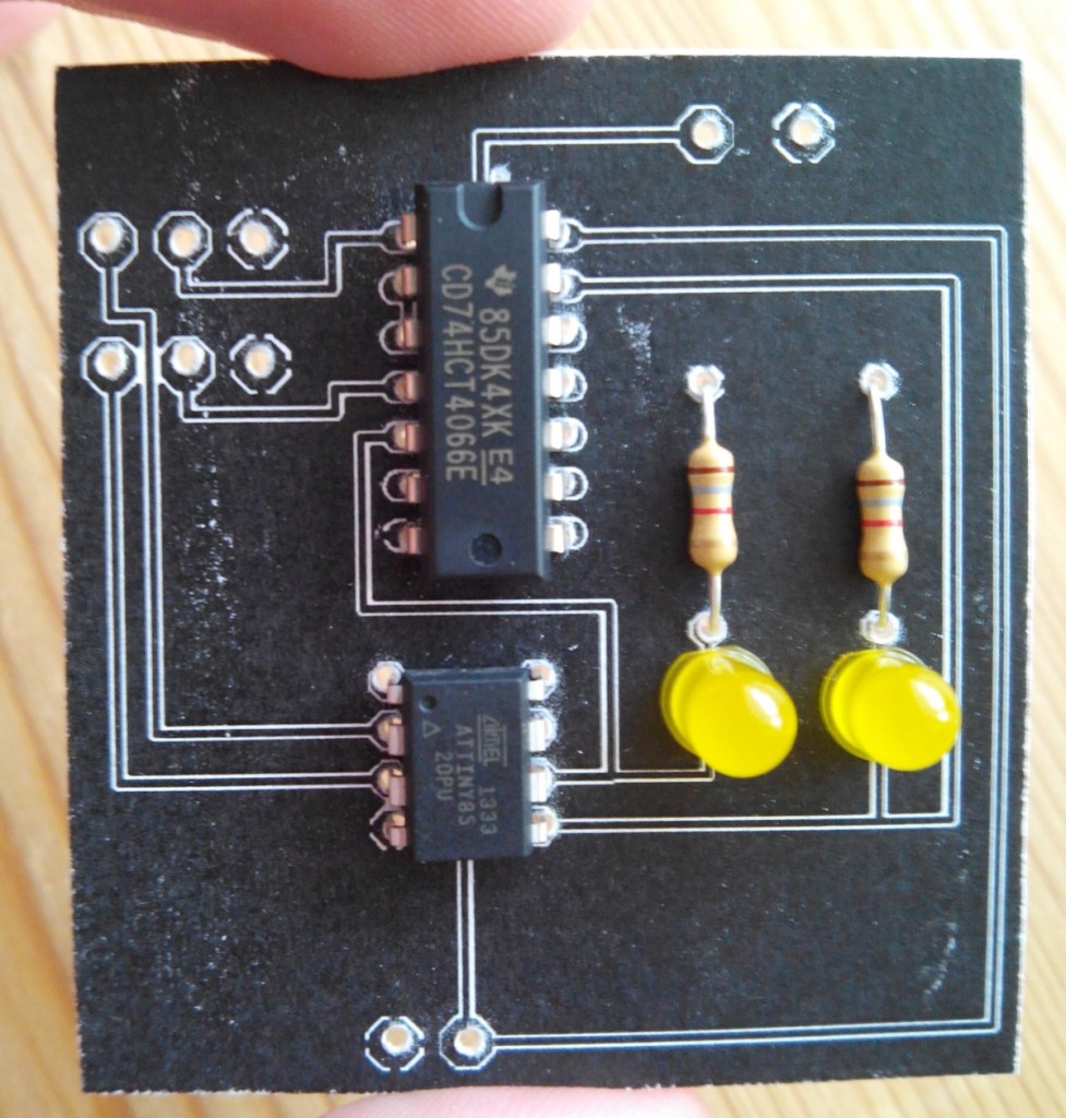
This is part of a series of blog posts in which I show you how I develop a DIY FPV diversity controller. In this step I have printed the first circuit to a cardboard. I use it to test fit the ATtiny85 micro controller, the 4066 electronic switch and the other components. Read more below…
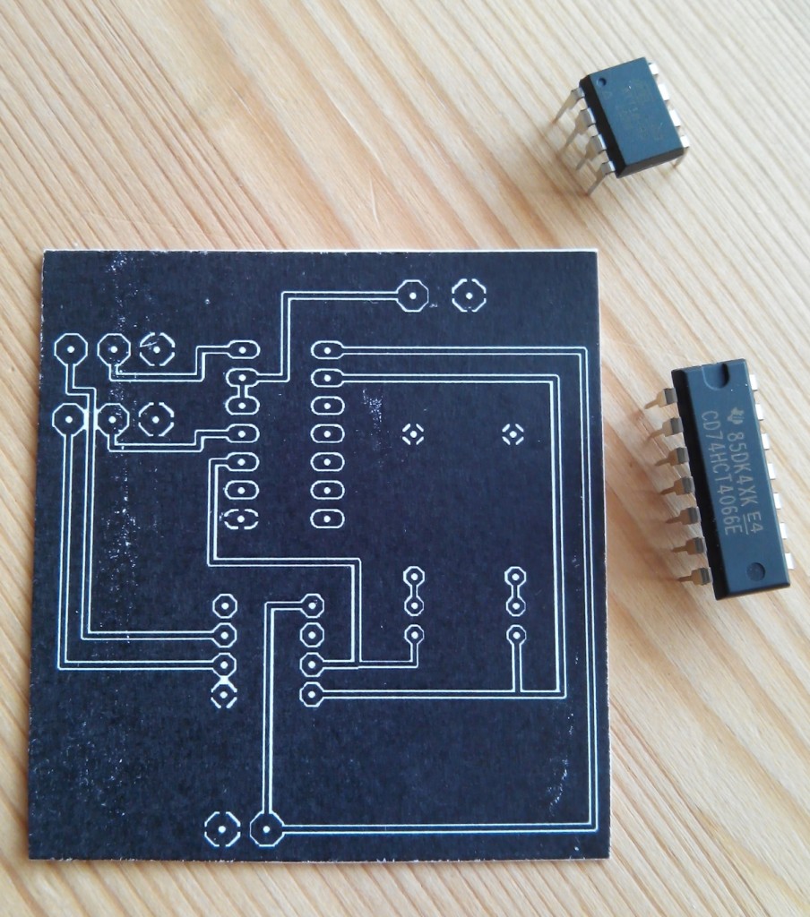
The first image shows the circuit board in 1:1 scale printed to a piece of cardboard. Note that I printed to the top of the cardboard so that I can better show you the details. In real the whole circuit would be on the bottom of the PCB. The whole thing is designed to use a single layer PCB. As all the components I use are through-hole components the circuit will be on the bottom.

The picture shows the printout of the toner mask that I will use to create the first test PCB. So everything that’s black here will be copper on the real PCB. This is exactly the circuit that I showed you in the previous step. You can find the eagle files here.

As you can see the PCB layout is perfect. Everything fits snugly but there is still enough room to run all the traces and to make soldering easy. Note: In real the trace will obviously run on the bottom side of the PCB. I just printed on the top for this test.
PS: Just in case you are wondering, those are not the correct resistors for the LEDs. For the test fitting I just grabbed the first two resistors I had laying around 🙂
At the moment I’m having a bit of trouble to get the toner transfer to work. Either the toner does not transfer to the copper correctly or the toner melts too much and blurs so that no traces are left after the transfer. I need to experiment more before I can fabricate the first test PCB …
Visit http://bitbucket.org/rgruber/fpv-diversity for all resources of this project.
You can find the source code, diagrams and photos there.
Just wondering if you have any more updates to this at all.
Am keen to know how its working etc etc
Thanks, Gav
Unfortunately i had very little time recently. I’m still stuck with the toner transfer (can’t get a clean transfer) to the PCB.
I have been looking to do this and was curious how you have been progressing?
No progress, unfortunately 🙁 I can not get the PCB to work the toner transfer always fails.
Do you have better luck masking PCBs?
I have no experience myself. From what I have read about making PCB’s it may be worth just sending your files to somewhere like OSHpark.com. Get them made so you can get on with the project. Of course, that’s assuming you are not doing it as a learning exercise?!
it might even be with it to buy the uncut cooper pcb sheets and cut or you’re design from that. it’s low tech and dirtier but it will make for the same end result
Hi Admin 🙂
It’s a pity that you have halted your project because of your troubles with toner transfer to make a simple PCB. I have made a few successfully by using toner transfer with laser printer onto hi gloss photo paper and using a hot clothes iron onto pre cleaned copper PCB. Etched in ferric chloride no preheating solution and not too hard at all.Here is a minimal Arduino PCB i made https://www.youtube.com/watch?v=5_s2Lxv9kqo Hey if I make you a PCB for your project you could continue with it. Are you interested Admin?
yea , i have a cnc cutter i use to make pcb, i used to etch and toner trans but it was crappy . if you find an old copy machine, and use magazine paper, set the copyer to super dark, and then when you iron on the pcb , get it hot as hell, and use lots of pressure pushing hard to really iron it on , let it cool, take it to the sink and soak it for a while the paper will fall to pieces now you can gently remove the rest of the paper, even if there is paper on the toner it will etch fine,
also ill be cutting this design out on my cnc soon so email me and ill cut you one ,
accounts@mywireguys.com
I just made this pcb using light exposed pcb and a up lamp. Came out great so thanks! The only thing I\’d suggest is beefing up some of those small pads because when you drill the holes with a 1mm bit there is very little left to solder.
Thanks, cool to hear that it worked out for you.
works great with that sketch. i used 2 eachine fpv receiver and your setup in ah hole pcb. loiks ugly but the maun thing that it wirks like it should